Pressure drop in a ventilation system refers to the reduction in air pressure as it moves through ducts, filters, and fans. This drop occurs due to air resistance and friction, which impede airflow. Air resistance increases with the speed of the air, a phenomenon known as pressure loss. The static pressure generated by a fan creates airflow that encounters resistance; as this resistance rises, airflow decreases. Friction losses in ducts, along with resistance from filters, silencers, heaters, valves, and dampers, all contribute to the overall pressure drop. Understanding how to calculate pressure drop on a building for ventilation is essential for managing these dynamics. The total pressure loss is the sum of all individual losses throughout the system. Accurate calculations are vital for ensuring proper airflow, enhancing system efficiency, preventing energy waste, and maintaining indoor air quality in HVAC systems.
Understanding Pressure Drop
In HVAC (Heating, Ventilation, and Air Conditioning), “pressure drop” refers to the reduction in air pressure as air moves through the system. This decrease is caused by friction against components such as ductwork, filters, and dampers, resulting in varying pressure levels at different points in the system. Understanding how to calculate pressure drop on a building for ventilation is essential, as it allows for the identification of resistance to airflow. When pressure at one point is higher than at another downstream, it indicates resistance to airflow. A significant pressure drop can signal problems like dirty filters, blockages, or poorly designed ductwork, which can reduce system efficiency and place additional strain on the fan motor.
Key Points About Pressure Drop in HVAC
The difference in air pressure between two points in an HVAC system is typically measured in Pascals (Pa).
Causes of Pressure Drop
Friction in Ductwork
As air flows through the ductwork, it comes into contact with the inner surfaces. This interaction creates friction, which is influenced by several factors, including the size, shape, and surface texture of the ducts. For instance, larger ducts may experience less friction than smaller ones, but if the surface is rough or has obstructions, it can still impede airflow. The design of the duct system—such as whether it is straight or contains multiple bends—also plays a critical role in determining how smoothly air can travel, impacting overall efficiency.
Dirty Filters
Air filters are essential for maintaining indoor air quality, but when they become clogged with dust, pollen, and other debris, they can significantly hinder airflow. This accumulation creates a barrier that the air must push through, leading to increased resistance. As a result, less air reaches the intended spaces, which can cause the HVAC system to work harder to maintain desired temperatures. Regular maintenance and timely replacement of filters are crucial to prevent this issue and ensure optimal performance.
Duct Fittings and Bends
The configuration of ductwork, including fittings and bends, can introduce additional resistance to airflow. Sharp turns, elbows, and transitions in duct size can disrupt the smooth flow of air, creating turbulence and increasing pressure drop. Each fitting adds a certain level of resistance, and when ducts are not designed with smooth transitions, the overall efficiency of the system suffers. Careful planning and design can minimize these effects by using gradual bends and appropriately sized fittings.
Dampers
Dampers are devices used to regulate airflow within the duct system. When dampers are partially closed, they restrict the amount of air that can flow through, which leads to increased pressure drop. This restriction can cause the fan to exert more effort to maintain the desired airflow, resulting in higher energy consumption and potential strain on the system. Properly adjusting and maintaining dampers is essential for achieving balanced airflow and maximizing system efficiency. Regular checks can help ensure that dampers are functioning as intended, allowing for optimal operation of the HVAC system.
Impact of High-Pressure Drop
Reduced Airflow
When pressure drop increases within an HVAC system, it can severely limit the airflow reaching different rooms and areas of the building. As air encounters resistance from dirty filters, duct bends, or obstructions, the system may struggle to push enough air through. This can result in some rooms receiving insufficient air, leading to discomfort for occupants. Inadequate airflow can also hinder the system’s ability to maintain desired temperature settings, making it difficult to create a consistent indoor climate throughout the space.
Increased Energy Consumption
As pressure drop rises, the fan motor must work harder to push air through the system. This increased workload not only strains the motor but also leads to higher energy consumption. The fan’s effort to overcome the resistance results in elevated energy bills, which can be significant over time. Inefficient operation due to high pressure drop means that the HVAC system is not only costing more to run but may also require more frequent repairs or replacements due to the added stress on components.
Uneven Heating and Cooling
High-pressure drop can lead to inconsistent airflow, which often results in uneven heating or cooling throughout the building. Some areas may become excessively warm, while others remain uncomfortably cold. This inconsistency creates hot and cold spots, undermining the overall comfort of the indoor environment. Occupants may find certain rooms difficult to use effectively due to temperature disparities, which can also increase reliance on supplemental heating or cooling solutions.
Equipment Wear and Tear
Persistent high pressure in the system exerts excessive strain on the fan motor and other components, leading to accelerated wear and tear. Over time, this can result in frequent breakdowns and the need for repairs, ultimately shortening the lifespan of the equipment. Routine maintenance becomes essential to mitigate these issues, but if the underlying causes of pressure drop are not addressed, the HVAC system may face continual operational challenges. Regular inspections and timely interventions can help prolong the life of the system and enhance its reliability.
Managing Pressure Drop
- Proper Duct Design: Choosing the right duct size and layout to minimize friction and bends.
- Regular Filter Maintenance: Cleaning or replacing filters according to manufacturer guidelines.
- Duct Sealing: Sealing leaks in the ductwork to prevent air loss and maintain pressure.
- System Balancing: Adjusting airflow in different zones to ensure even distribution throughout the building.
Key Concepts in Ventilation
Before diving into calculations, including understanding how to calculate pressure drop on a building for ventilation, familiarize yourself with:
Airflow Rate (CFM)
The airflow rate, measured in cubic feet per minute (CFM), refers to the volume of air that moves through the HVAC system at any given time. This metric is crucial for understanding how effectively the system circulates air throughout a building. A higher CFM indicates a greater volume of air being delivered, which is essential for maintaining comfort levels and ensuring adequate ventilation. Properly calculating and adjusting the airflow rate is vital for meeting the heating and cooling demands of different spaces, as well as for optimizing energy efficiency.
System Resistance
System resistance refers to the opposing forces encountered by air as it travels through the ductwork and other components of the HVAC system. This resistance can arise from several factors, including friction against the duct surfaces, bends and turns in the ducting, and obstructions such as dirty filters or closed dampers. Understanding system resistance is essential for designing an efficient HVAC system; excessive resistance can lead to reduced airflow, increased energy consumption, and strain on the fan motor. Analyzing and minimizing these resistance factors is key to achieving optimal performance.
Balanced Pressure
Maintaining balanced pressure within the HVAC system is crucial for ensuring consistent and efficient airflow. Balanced pressure means that the pressure in the supply ducts is properly matched with the pressure in the return ducts, allowing for smooth air circulation without excessive strain on the system. Achieving this balance helps to prevent issues such as uneven heating and cooling, noise, and energy inefficiency. Regular monitoring and adjustments can help maintain balanced pressure, contributing to a comfortable indoor environment and enhancing the overall performance of the HVAC system.
Tools and Equipment Needed
Manometer or Differential Pressure Gauge
A manometer or differential pressure gauge is a crucial instrument used to measure pressure readings within an HVAC system. This tool can detect differences in pressure between two points, allowing technicians to assess pressure drops across various components such as filters, ducts, and fans. Understanding these pressure readings is vital for diagnosing potential issues, ensuring that the system operates efficiently, and maintaining balanced airflow. Manometers come in various types, including digital and analog models, offering versatility for different measurement needs.
Anemometer
An anemometer is an essential device for measuring airflow within the ventilation system. It quantifies the velocity of air moving through ducts and openings, typically expressed in cubic feet per minute (CFM). By using an anemometer, HVAC professionals can determine whether the system is delivering the appropriate amount of air to each space. These instruments can vary in design, with options ranging from handheld models to more sophisticated stationary units, each providing valuable data for optimizing system performance and ensuring effective ventilation.
Measuring Tape
A measuring tape is a fundamental tool for accurately determining duct dimensions and other physical parameters within the HVAC system. Precise measurements of duct length, width, and height are essential for calculating airflow rates and pressure drops accurately. Using a measuring tape helps ensure that HVAC systems are designed and installed correctly, which is critical for achieving optimal performance. Accurate dimensions also play a crucial role in the selection of components and materials, contributing to the overall efficiency and effectiveness of the ventilation system.
- Optional: HVAC calculation software for automated estimates.
How to Calculate Pressure Drop on a Building for Ventilation
Step 1: Measure Airflow Rate
Begin by using an anemometer to measure the airflow rate in cubic feet per minute (CFM) at various points within the ventilation system. This data is crucial for understanding how effectively air is being distributed. Conduct measurements at key locations, such as supply ducts, return ducts, and at the outlets of grilles or diffusers, to get a comprehensive view of airflow throughout the system.
Step 2: Determine Duct Dimensions
Next, accurately measure the dimensions of the ducts, including their diameter and length. It’s important to note the material type of the ducts, as variations in surface roughness can significantly impact friction losses. For example, smooth metal ducts will have different resistance characteristics compared to flexible or rough-surfaced ducts. Document these measurements for use in subsequent calculations.
Step 3: Identify Friction Losses
Consult friction loss tables specific to the duct material and airflow rate to determine the resistance encountered due to friction. These tables provide essential information that correlates airflow with expected pressure loss, allowing you to quantify how much energy is lost as air travels through the ducts. Ensure that the tables you reference match the duct size and material you are working with for accurate results.
Step 4: Account for Fittings and Accessories
In addition to friction losses, it’s essential to calculate the pressure drops caused by fittings and accessories, such as bends, elbows, and dampers. Use their respective loss coefficients to determine how much additional pressure drop each fitting contributes to the system. These coefficients can often be found in manufacturer specifications or engineering handbooks, and they provide a way to quantify the impact of these components on overall system performance.
Step 5: Calculate Total Pressure Drop
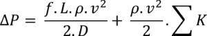
Finally, the friction losses and the losses from fittings are combined to arrive at the total pressure drop in the ventilation system. The formula for this is:
Total Pressure Drop = Friction Loss + Fitting Loss
This total will give you a comprehensive understanding of the pressure dynamics within the system, helping you identify areas for improvement and ensuring that the HVAC system operates efficiently.
Formula for How to Calculate Pressure Drop on a Building for Ventilation
Calculating pressure drop in a ventilation system is essential for ensuring adequate airflow and system efficiency.
![]()
- : Total pressure drop (Pa or psi).
- f: Friction factor (dimensionless, depends on duct material and flow regime; use the Moody Chart for exact values).
- L: Length of the duct (m or ft).
- : Air density (kg/m^3 or lb/ft^3, dependent on temperature and pressure).
- v: Air velocity (m/s or ft/s).
- D: Hydraulic diameter of the duct (m or ft).
- K: Loss coefficient for fittings, bends, dampers, or other components (dimensionless, determined from manufacturer data or guidelines).
Steps to Calculate:
- Friction Loss (f L term): Calculate the pressure loss due to friction along the duct length using the Darcy-Weisbach equation. Friction factor f can be found using the Reynolds number (Re) and relative roughness (ϵ/D).
- Dynamic Loss (K term): Calculate the losses due to changes in direction, contraction, expansion, or obstacles like filters. Use tabulated K-values specific to each fitting.
- Sum Losses: Add up the contributions from all components (friction losses and dynamic losses) to get the total pressure drop.
Example
To calculate the pressure drop in a ventilation system, we have the following parameters: the duct length (L) is 20 meters, the air velocity (v) is 5 meters per second, and the duct diameter (D) is 0.5 meters. The air density (ρ) is 1.2 kilograms per cubic meter, and the friction factor (f) for the smooth duct is 0.02, derived from the Moody chart. Additionally, there is a 90° elbow in the system, with a loss coefficient (K) of 0.5.
Using these values, we can compute the pressure drop due to friction along the duct and the dynamic loss at the elbow, then sum them to find the total pressure drop in the system.
Step 1
Calculate the friction loss using Darcy-Weisbach formula for frictional pressure drop
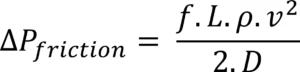
After substituting the values the pressure drop due to friction is 12 Pascal.
Step 2
Calculate dynamic loss at the elbow using the formula for dynamic pressure drop:
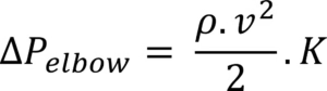
After substituting the values the dynamic pressure loss at the elbow is 7.5 Pascal.
Step 3
The total pressure loss or pressure drop is the sum of these values which is 12 + 7.5 =19.5 Pascal.
Interpreting the Results
Once you have calculated the pressure drop in your ventilation system, it’s important to compare your findings against established acceptable thresholds.
Assessing Energy Efficiency
Lower pressure drops are generally desirable, as they contribute to improved energy efficiency within the HVAC system. When pressure drop is minimized, the system can operate more effectively, allowing the fan to use less energy to maintain proper airflow. This efficiency not only reduces operating costs but also extends the lifespan of the equipment by minimizing strain on the fan motor and other components. By maintaining low-pressure drops, you can enhance overall system performance and achieve better indoor air quality.
Identifying Potential Issues
Conversely, excessive pressure drops can indicate underlying problems within the system that may require attention. High-pressure drops may signal issues such as clogged filters, improperly sized ducts, or excessive bends and fittings that hinder airflow. If the pressure drop exceeds acceptable limits, it may be necessary to consider a redesign or upgrade of the system. This could involve resizing ducts, replacing filters, or reconfiguring the layout to reduce resistance to airflow. Addressing these issues proactively can prevent further inefficiencies and ensure consistent, reliable performance of the HVAC system.
Common Mistakes to Avoid
When calculating pressure drop in an HVAC system, including knowing how to calculate pressure drop on a building for ventilation, several common mistakes can lead to inaccurate assessments and compromised system performance. Here are some key pitfalls to avoid::
Incorrect Duct Measurements
One of the most critical errors is taking inaccurate measurements of duct dimensions. Duct length, diameter, and shape are essential for calculating airflow and pressure drop. Even small discrepancies can lead to significant variations in the results. It’s important to use precise measuring tools and techniques, ensuring that all measurements account for any irregularities in the ductwork, such as bends or expansions. Failing to measure accurately can result in an inefficient system that does not deliver the desired airflow.
Overlooking Minor Fittings
Another common oversight is neglecting to consider minor fittings, such as dampers, transitions, and small elbows. While these components may seem insignificant, they can significantly impact airflow and pressure drop. Each fitting introduces resistance that can alter the system’s performance. Ensure that all fittings are included in your calculations, as they contribute to the overall pressure dynamics. Ignoring these details can lead to an incomplete analysis and potentially result in overestimating the system’s efficiency.
Ignoring System Balancing for Multi-Zone Systems
In multi-zone HVAC systems, proper balancing is essential for maintaining consistent airflow across different areas. Failing to account for the need to balance airflow between zones can lead to uneven heating and cooling, resulting in some areas receiving too much air while others get too little. It’s vital to evaluate each zone individually and make adjustments to dampers and airflow rates to ensure that the system operates efficiently and provides comfort throughout the entire building. Ignoring this aspect can compromise the overall effectiveness of the HVAC system and diminish indoor air quality.
Case Studies and Examples
Example 1: Commercial Office HVAC System
In a commercial office setting, an HVAC system was found to have a calculated pressure drop of 0.8 in H2O. This level of pressure drop indicated that the system was experiencing significant resistance, likely due to the presence of high-resistance fittings such as sharp elbows and restrictive dampers.
- To address this issue, the facility management team undertook an optimization project that involved replacing these high-resistance fittings with more efficient alternatives designed to reduce airflow resistance. As a result, the pressure drop was significantly lowered, leading to improved airflow throughout the office spaces. This optimization not only enhanced comfort for the occupants but also increased the energy efficiency of the system, ultimately reducing operational costs and extending the lifespan of the HVAC equipment.
Example 2: Residential Ventilation System
In a residential setting, a ventilation system was discovered to exceed a pressure drop of 1 in H2O, which is considered excessive for optimal performance. This high-pressure drop was primarily attributed to the use of ductwork with numerous bends and transitions that disrupted smooth airflow.
- To remedy this situation, the homeowners opted for completely redesigning the ventilation system. They replaced the existing ducts with smoother, larger diameter ducts that minimized turns and bends. This redesign not only reduced the pressure drop significantly but also improved the overall efficiency of the system. The result was a more balanced airflow throughout the home, eliminating hot and cold spots and enhancing indoor air quality. Additionally, the homeowners experienced lower energy bills as the system operated more efficiently.
Conclusion
Understanding and managing pressure drops in ventilation systems is crucial for optimal HVAC performance. Pressure drop refers to the reduction in air pressure as it flows through ducts, filters, and other components, primarily driven by friction and resistance. Accurate calculations of pressure drop are essential for ensuring sufficient airflow, enhancing energy efficiency, and maintaining indoor air quality. Knowing how to calculate pressure drop on a building for ventilation is fundamental for achieving these goals.
High-pressure drops can lead to reduced airflow, increased energy consumption, uneven heating and cooling, and accelerated wear on system components. By carefully measuring duct dimensions, considering all fittings, and ensuring proper system balancing, HVAC professionals can mitigate these issues. Regular maintenance, including filter replacements and duct sealing, further supports system efficiency.
Ultimately, addressing pressure drops not only improves comfort for occupants but also contributes to significant cost savings and a more sustainable operation of HVAC systems. Proactive management and optimization strategies will lead to a reliable, efficient, and effective ventilation system.
FAQs
- What is a pressure drop in ventilation?
The loss of air pressure as it flows through ducts and fittings. - Why is pressure drop important?
It impacts airflow, energy efficiency, and system effectiveness. - What tools do I need to measure pressure drop?
A manometer, anemometer, and measuring tape. - How do bends affect pressure drop?
Bends increase turbulence and resistance, raising pressure drop. - What is friction loss?
Pressure loss is caused by air rubbing against duct walls. - How do fittings contribute to pressure drop?
Fittings disrupt airflow, adding resistance measured by loss coefficients. - What is the acceptable pressure drop range?
It varies, but 0.5–1 in H2O is common for efficient systems. - Can software help with how to Calculate Pressure drop on a Building for Ventilation?
Yes, HVAC software automates and simplifies calculations. - What if my pressure drop is too high?
Optimize by reducing bends, using smoother ducts, or upgrading components. - How often should I check pressure drop?
Annually or during system inspections.
If you like reading this post you may also like


Thanks for reading, for more interesting articles, visit our homepage.